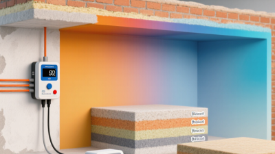







Measuring heat flow sounds straightforward: place a sensor on a surface and read the result. But reliable measurements depend on more than the display. A poorly matched range, sensor size, or mounting method can distort readings before analysis begins. Small details matter. Surface curvature, contact pressure, insulation, and temperature limits all influence performance. Even a thin adhesive layer may change thermal contact, so installation deserves as much attention as the datasheet. Fit matters. The omega heat flux sensor may suit one test setup well and another poorly; the application decides.
This guide presents seven practical tips for comparing sensor options, matching measurement range to expected heat flow, and checking sensitivity, size, output, and operating conditions. It also highlights calibration records and mounting choices, details that are easy to overlook when time is short. Not every specification tells the whole story. A catalog value cannot replace a careful look at the test surface and heat path. Before purchase, compare the sensor’s documented limits with the actual setup, and confirm which accessories the measurement requires. If uncertainty remains, ask the manufacturer or a qualified applications specialist. That check can prevent a costly rerun. The goal is not to find the most elaborate sensor, but one that provides stable, interpretable data under real conditions.
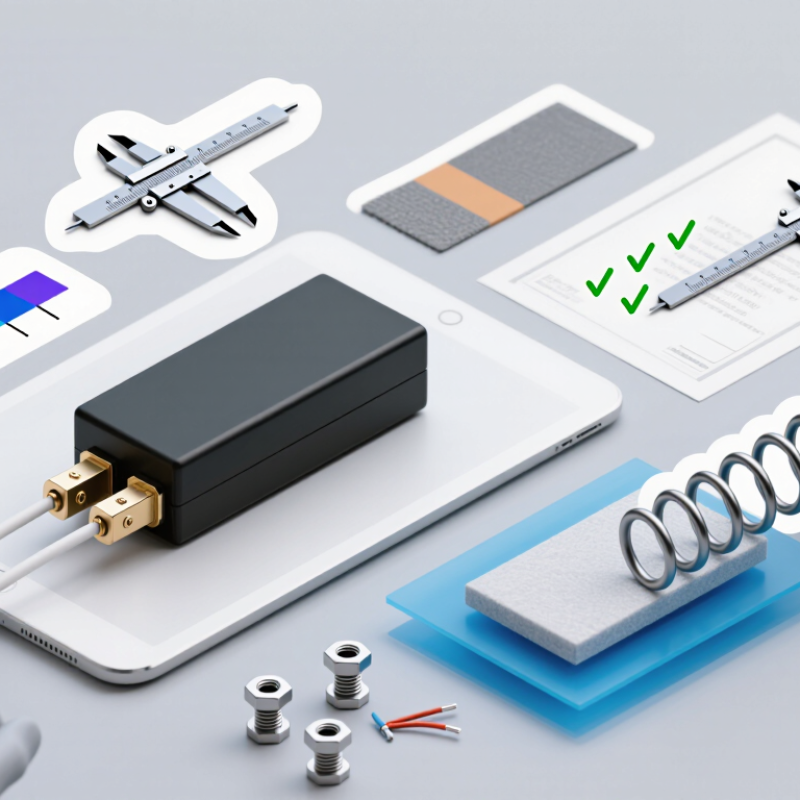
Before choosing a heat flux sensor, define the measurement task. Set the expected flux range, heat-flow direction, surface temperature, and allowable uncertainty. Peak and average values can differ sharply during startup, so size for transients, not just steady operation. Record whether the sensor will sit on a wall, pipe, or test plate. Curvature and contact layers can change the thermal path. Small gaps matter. Check that sensitivity, response time, calibration range, and output match the data logger. A written uncertainty budget also makes assumptions easier to spot.
For building-envelope measurements, ISO 9869-1:2014 specifies a useful benchmark: collect readings at intervals of 30 minutes or less, over a measurement period of at least 72 hours.
This protocol is not universal for fast industrial tests. It does show why sampling interval and test duration belong in the requirements from the start. Check calibration traceability and uncertainty against the expected signal. Low flux can be unforgiving: a sensor that barely resolves it may produce tidy but misleading numbers. Verify mounting with a repeatable contact method, and document any insulation placed around the sensor. Even careful setups can disturb the surface. Record that limitation.

Choose a heat-flux sensor for the temperatures and flux levels it will actually encounter. Estimate the normal reading and brief peaks, then select a range that captures both without clipping. A sensor with an unnecessarily broad range may produce a smaller output signal per unit of heat flux. Check sensitivity against your logger’s resolution and electrical noise. The signal should remain distinguishable from drift, even during low-flux periods. Small details matter: contact pressure, surface curvature, and insulation around the sensor can all affect readings.
Accuracy and sensitivity are different. Sensitivity describes output per unit of heat flux; accuracy describes closeness to the true value, including calibration uncertainty. Read the specification conditions carefully. A stated accuracy may apply only within a particular temperature range or calibration setup. ASTM C1130, the practice for calibrating thin heat-flux transducers, is a useful reference when comparing calibration methods. For building measurements, ISO 9869-1:2014 specifies a minimum 72-hour measurement period for the heat-flow-meter method. That is a reminder that a stable result may take time. Match the sensor’s range to expected peaks, its sensitivity to the measurement system, and its accuracy to the decision being made. I would still verify the setup on the actual surface; neat laboratory numbers can be a little optimistic.
Match sensor range, sensitivity, and accuracy to the application.
How to use this chart: These are approximate planning examples, not universal limits; actual heat flux varies with conditions. Choose a range that covers expected peaks, check that sensor sensitivity provides enough signal for your readout, and confirm accuracy and calibration uncertainty meet your measurement needs.
A heat-flux sensor should fit the surface, not just the measurement range. For a broad, flat panel, a larger sensor can average local variations and provide a steadier reading. On a narrow pipe or curved housing, a smaller, flexible design may sit more evenly. Fit matters. A sensor that bridges a curve can leave tiny air gaps, which distort heat transfer and readings.
Consider how heat moves through the assembly. A surface-mounted sensor measures heat passing through its sensing layer, so its thickness and contact materials can alter the local thermal path. Use a thin, compatible mounting layer, apply even pressure, and keep wires from pulling the sensor out of position. Embedded designs suit some layered materials, but they require planning before assembly. Retrofitting them is not always practical.
Match response time and temperature limits to the process. Rapid heating cycles call for a sensor that responds quickly; slow, steady conditions may allow a more robust construction. Check whether the sensor can withstand the surface temperature, humidity, vibration, and cleaning routine. Keep it stable. Installation details are easy to underestimate, and even careful mounting may not remove every source of error. Record the placement and mounting method so later readings can be compared fairly.
Tip: Check the sensor’s temperature and heat-flux limits against the actual test conditions. A chamber’s air temperature may differ from the sensor’s contact surface temperature. Include brief start-up peaks, not just steady operation. If the sensor approaches its limit, readings may drift or the sensor may be damaged. Small details matter.
Tip: Check the full measurement chain before ordering. Confirm that the instrument accepts the sensor’s output type and voltage range. Review input impedance, connector type, polarity, and cable length. A connector that fits is not enough. Long leads can pick up electrical noise, especially near motors or heaters, so use suitable shielding and routing.
Also consider how the sensor will be mounted. Curved surfaces, uneven pressure, or a thick layer of adhesive can affect thermal contact and measurements. Check whether the instrument can record at the response speed your test requires. It is easy to focus on sensor accuracy and overlook these practical limits. That check is worth repeating with the actual setup, since a specification sheet cannot reveal every installation problem.
7 Tips for Choosing an Omega Heat Flux Sensor
Calibration, mounting, and maintenance deserve attention before a sensor reaches the test surface. Check its calibration range against the heat flux you expect, not just the instrument’s maximum rating. Ask how calibration uncertainty is reported and whether the calibration conditions resemble your setup. A sensor calibrated under different temperatures or contact conditions may behave differently in practice. Small gaps matter.
Plan the mounting method early. A thin, even layer of suitable thermal interface material can improve contact, but excess material may distort readings. Keep the sensor flush with the surface, avoid bending its active area, and route lead wires so they do not tug on the mount. Record the surface material, mounting pressure, and ambient conditions; those details help explain changes later. I have seen mounting notes get skipped when a test is rushed. That is easy to regret.
Set a maintenance interval based on use, not guesswork. Inspect the sensing face for scratches, residue, or lifted edges, and check cables for worn insulation. Compare readings with a stable reference or repeatable test periodically. Keep a log of drift, repairs, and recalibration dates. If readings shift after remounting, do not assume the sensor failed; contact and alignment may have changed. Still, a maintenance schedule can be imperfect at first. Review it after real operating cycles, then adjust it.