








How to Choose the Right Heat Flux Meter?

Choosing the right heat flux meter begins with understanding the measurement, not comparing product names. Heat flux describes thermal energy moving through a surface. As heat-transfer authority Dr. John H. Lienhard V explains, “Heat transfer is the transport of thermal energy from one location to another.” That movement may occur through a furnace wall, building envelope, battery pack, or insulated pipe.

A suitable heat flux meter must match the application’s temperature, range, surface, and installation conditions. A sensor placed on a curved metal pipe may respond differently from one bonded to a flat composite panel. Adhesive thickness, contact pressure, airflow, and surface coatings can all influence the reading. Small details matter.

Start with the expected heat-flow direction and approximate magnitude. Then examine the sensor’s sensitivity, response time, calibration method, and operating temperature. Water-cooled sensors may suit intense laboratory testing. Thin surface sensors can be better for temporary field measurements. No choice is perfect.

Reflection is necessary here. A high sensitivity rating does not automatically produce a better result. It may also increase noise or installation demands. Calibration traceability supports confidence, but it cannot correct poor placement. The instrument only reports what the measurement setup allows it to see.

This guide explains how to evaluate a heat flux meter with practical judgment. It considers accuracy, durability, data collection, and real-world handling. The goal is not to select the most advanced device. It is to select the sensor that produces dependable evidence under your actual conditions.
How to Choose the Right Heat Flux Meter?

Define the Measurement Goals and Heat Flux Conditions

How to Choose the Right Heat Flux Meter?

Define the measurement goal before comparing sensor specifications. Do you need a wall U-value, a thermal bridge profile, or furnace surface loss? Each task requires different accuracy, response time, and installation methods. The International Energy Agency reports that buildings consume about 30% of global final energy. The U.S. Energy Information Administration’s 2020 Residential Energy Consumption Survey attributes 42% of household energy use to space heating. Small measurement errors can therefore influence meaningful efficiency decisions.

Describe the heat flux conditions in writing. Record expected flux range, heat-flow direction, surface temperature, air temperature, and exposure time. Note whether the surface is steady, changing, wet, dusty, or exposed to sunlight. ISO 9869-1 recommends extended in-situ measurements for building elements, because short readings can misrepresent thermal performance. ASTM C1046 also emphasizes proper sensor attachment and temperature control. A thin sensor may respond quickly, but it can disturb a fragile surface. A thicker sensor may be stronger, yet slower. That trade-off is easy to overlook. Place the sensor on a representative area, not the most convenient spot. Avoid joints, fasteners, shadows, and obvious defects unless those are the actual study targets. Check calibration before and after testing. A tidy dataset can still be wrong. Review the mounting pressure, contact layer, and environmental changes before trusting the final value.

Compare Heat Flux Meter Types and Sensing Technologies

How to Choose the Right Heat Flux Meter?

Choosing a heat flux meter starts with the measurement environment, not the instrument’s advertised range. Consider temperature, expected flux, surface shape, response time, and installation pressure. A sensor that performs well on a flat test panel may behave differently on curved metal. Short tests reveal weaknesses.

Thermopile sensors measure temperature differences across a calibrated thermal resistance. They suit steady measurements and offer useful sensitivity over broad applications. Gardon-type gauges respond quickly to intense radiant heat, making them practical for furnaces, flames, and high-temperature testing. Thin-film sensors are small and fast, but they can drift when exposed to repeated thermal cycling. Response time matters.

For building envelopes or insulation studies, a surface-mounted conductive sensor may be appropriate. For combustion research, a water-cooled or high-range design can better manage severe heat loads. Sensing technology also affects contact resistance, calibration stability, and signal noise. Check whether the sensor measures total, convective, or radiative heat flux.

In field testing, careful mounting often matters more than small differences in specifications. Dust, air gaps, uneven surfaces, and loose adhesive can distort readings. Calibration comes first. I have seen measurements questioned because the sensor was accurate, but poorly positioned. That is an uncomfortable lesson. Verify the installation method, calibration date, uncertainty, and data logger compatibility before trusting the result.

Evaluate Accuracy, Range, Response Time, and Calibration

Accuracy starts with installation, not the display.

Check uncertainty across the complete working range. Some meters quote percentage of reading, while others quote percentage of full scale. That difference matters at low heat flux. NIST Technical Note 1297 recommends building an uncertainty budget rather than trusting one headline number. Include sensor calibration, surface contact, temperature gradients, wiring, and data acquisition. A clean number can still be wrong.

Range should cover expected minimum and peak values without operating near saturation. Response time also deserves attention. A slow sensor may flatten short thermal events, especially near doors, heaters, or changing outdoor conditions. Match the sensor time constant with the logging interval.

ISO 9869-1:2014 specifies field heat-flow measurements over at least 72 hours, with regular readings; longer testing can reveal daily thermal patterns. Calibration should be traceable, documented, and performed under conditions close to actual use.

ASTM C1130 provides a recognized practice for calibrating thin heat-flux transducers. Check the calibration date, stated uncertainty, reference conditions, and correction factors. Recalibration may be sensible after mechanical shock, contamination, cable repair, or prolonged exposure. Still, calibration alone is not enough. A poorly mounted sensor remains a weak measurement.

Select the Right Sensor Design for Your Test Environment

How to Choose the Right Heat Flux Meter?

Select the Right Sensor Design for Your Test Environment

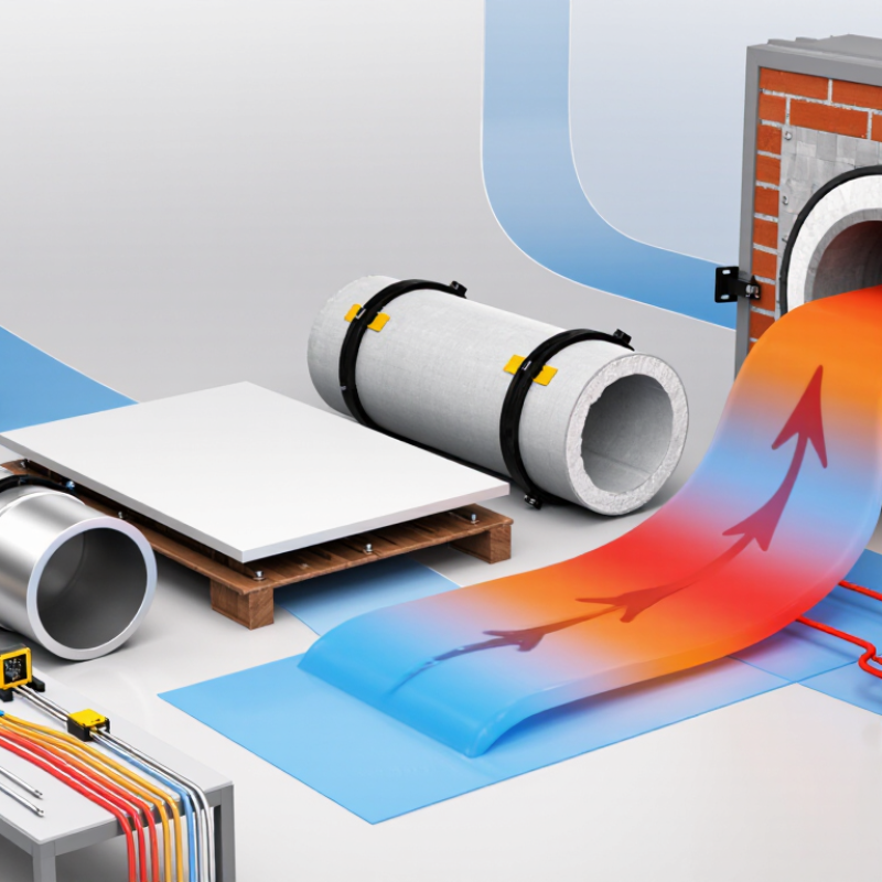
A heat flux meter should match the test environment, not just the expected heat range. In furnace testing, choose a sensor that tolerates high surface temperatures and strong thermal radiation. A water-cooled design can protect the sensing element during long exposures. For fast transients, a thin, low-mass sensor usually responds more quickly. However, it may be more sensitive to mounting errors and surface damage.

Consider the contact surface carefully. A rough metal wall, curved pipe, and coated panel each transfer heat differently. Use a sensor with suitable thickness, flexibility, and thermal resistance. In airflow studies, exposed sensors can disturb the flow and produce misleading readings. Shielding may reduce this effect, but it can also change the local heat transfer. This trade-off is easy to underestimate. I have seen stable data become questionable after a small mounting adjustment.

Tips: Check the calibration range, response time, operating temperature, and measurement uncertainty. Match the sensor footprint to the test area. Keep the sensing face flush with the surface. Avoid trapped air, loose adhesive, and uneven pressure. Record installation details with every test. A traceable calibration certificate supports reliable comparisons, but calibration alone cannot correct poor placement. When conditions change, repeat a short verification test. Perfect readings are rare. Careful setup matters more than impressive specifications.

Verify Installation, Data Collection, and Long-Term Reliability

Choosing the right heat flux meter starts with verifying its installation, not just its specifications. Select a sensor suited to the surface temperature, material, and expected heat flow. Clean the contact area carefully. Remove dust, paint flakes, and air gaps. Use a suitable thermal interface layer, then apply even pressure without crushing the sensor.

Check the cable path before recording data. Keep cables away from heaters, sharp edges, and strong electrical sources. Confirm the data logger’s sampling interval, time settings, and measurement range. A ten-minute interval may suit slow building studies, while faster systems need shorter sampling. Record surface temperature, room conditions, sensor position, and installation time. Keep it traceable.

A reliable installation needs a baseline check. Compare readings from similar locations when possible. Watch for sudden jumps, flat lines, or unexplained noise. These signs may indicate loose contact, damaged wiring, or incorrect settings. A small mistake can distort weeks of data. I have found that simple photographs and field notes prevent many later disputes. Still, no installation is perfect. Recheck the sensor after vibration, seasonal changes, or maintenance work. Review calibration records regularly, and estimate uncertainty instead of hiding it. Long-term reliability depends on repeated inspection, sensible data review, and honest attention to small changes.

How to Choose the Right Heat Flux Meter? - Verify Installation, Data Collection, and Long-Term Reliability

Selection Area Verification Point Recommended Technical Guidance Practical Acceptance Target
Measurement Range Expected heat-flux range of the application Select a meter whose calibrated range covers the expected minimum and maximum heat flux. Avoid operating continuously near the upper limit because overloads and thermal damage can reduce measurement reliability. Normal operating values should generally remain below 70–80% of the rated measurement range.
Measurement Accuracy Uncertainty and calibration specification Compare total measurement uncertainty, not only the sensor sensitivity. Include calibration uncertainty, temperature dependence, installation effects, data-acquisition error, and repeatability. Use a meter whose stated uncertainty is no more than one-third of the allowable project error.
Sensor Construction Thermopile or thin-film sensor design Thermopile sensors are commonly used for surface heat-flux measurements because they generate a low-level voltage proportional to heat flow. Thin, low-thermal-resistance designs reduce disturbance of the tested surface. Choose a sensor thickness and thermal resistance that do not significantly alter the heat-transfer path.
Surface Compatibility Contact with the test surface Confirm that the sensor can be bonded, clamped, or embedded without creating air gaps. The contact surface should be clean, flat, and free from loose coatings or contamination. No visible air gap; sensor faces the heat-transfer direction and remains fully supported.
Installation Method Attachment, alignment, and cable routing Use a uniform, thin thermal interface where permitted. Route cables away from direct heat paths, protect them from tension, and avoid bending the sensor body or cable junction. Stable mechanical contact, no cable strain, and no exposed path for parasitic heat transfer.
Thermal Disturbance Effect of the meter on the measured system Check sensor thickness, thermal conductivity, and surface emissivity. On radiative surfaces, the sensor finish should be compatible with the surrounding surface or corrected using an appropriate radiation model. The installation should not materially change local temperature or boundary conditions.
Temperature Range Operating temperature of the sensor and cable Verify the complete assembly rating, including adhesives, cable insulation, connectors, and protective layers. Temperature limits may differ between the sensing element and the cable. Allow a safety margin of at least 10–20 °C below the lowest rated component.
Response Time Transient response and sampling interval A meter with lower thermal mass generally responds faster. For transient tests, select a sensor whose response time is short compared with the event being measured. Use a sampling rate at least 5–10 times faster than the highest frequency of interest.
Signal Output Voltage level, sensitivity, and electrical noise Heat-flux meters often produce millivolt- or microvolt-level signals. Use shielded cables, suitable input impedance, stable excitation where required, and differential measurement to reduce electrical interference. Signal-to-noise ratio should be high enough that noise remains below 1–5% of the smallest value being reported.
Data Collection Logger resolution, channel configuration, and units Record raw voltage, calibration sensitivity, calculated heat flux, sensor temperature when available, timestamp, and test conditions. Store the original data separately from processed results. Use at least 16-bit analog-to-digital conversion for low-level signals and document the conversion equation.
Sampling Strategy Averaging, filtering, and synchronization Select the sampling interval according to the thermal dynamics. Apply filtering only after preserving the raw signal, and synchronize heat-flux data with temperature, pressure, flow, or power measurements. Keep unfiltered raw data and record the filter type, cutoff frequency, and averaging period.
Calibration Traceability and calibration interval Use a calibration certificate that identifies sensitivity, uncertainty, calibration conditions, and validity date. Recalibrate after mechanical damage, overheating, major installation changes, or unexplained drift. Maintain calibration records and verify zero or baseline response before and after each test series.
Long-Term Stability Drift, aging, and repeated thermal cycling Assess sensitivity change over time, especially when the meter is exposed to high temperature, moisture, pressure, vibration, or repeated thermal cycles. Trend calibration results; investigate any sensitivity change that exceeds the project uncertainty budget.
Environmental Protection Moisture, dust, chemicals, vibration, and pressure Confirm enclosure and connector protection for the test environment. Protect the sensing face without covering the active measurement area or changing its thermal properties. Use environmental protection appropriate to the application and verify performance under representative conditions.
Installation Verification Initial functional and continuity checks Inspect the sensor, cable, connectors, and attachment. Check electrical continuity, polarity, signal stability, and baseline output before applying the heat load. Pass before test No intermittent connection, abnormal noise, or unexplained baseline offset.
Data Quality Plausibility and repeatability of results Compare readings with an energy balance, a reference measurement, or a calculated estimate. Repeat measurements after repositioning when practical to identify local surface effects. Results should be physically plausible and repeatable within the defined project uncertainty.
Maintenance Storage, cleaning, and inspection Store the meter flat and protected from moisture, impact, contamination, and excessive temperature. Inspect the sensing surface and cable before reuse; do not abrade the active area. Keep a usage log and remove the meter from service if the surface, cable, or connector is damaged.
Documentation Traceability of each measurement Document sensor identification, location, orientation, attachment method, surface temperature, calibration factor, logger settings, environmental conditions, and data-processing steps. Another qualified engineer should be able to reproduce the setup from the test record.