










Why Use a Heat Flow Meter?
Why Use a Heat Flow Meter?
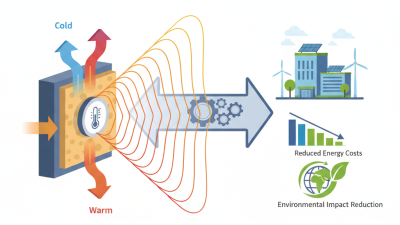
A wall can feel warm and still lose heat through hidden paths. A heat flow meter helps quantify that transfer instead of relying on touch or guesswork. The need is practical: the 2023 Global Status Report for Buildings and Construction, published by UNEP and GlobalABC, estimates that buildings use 34% of global energy and produce 37% of energy- and process-related carbon dioxide emissions. Better measurements can help engineers evaluate insulation and identify where thermal performance needs attention.
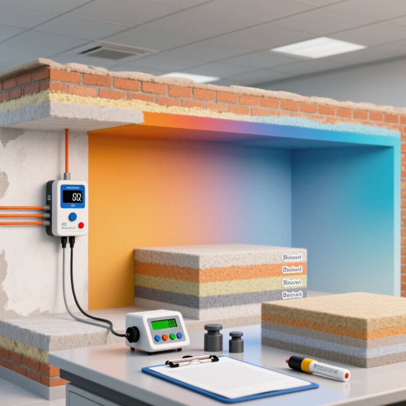
In a laboratory, a heat flow meter apparatus measures heat passing through a material sample under controlled conditions. ASTM C518 and ISO 8301 describe relevant steady-state test methods. The setup matters: sensor contact, temperature difference, sample thickness, and stable conditions can all affect results. Small details count. As heat-transfer textbook authors Frank P. Incropera and David P. DeWitt put it, “Heat transfer is thermal energy in transit due to a temperature difference.” A meter makes that transfer measurable, but it does not explain every cause of heat loss by itself. A thermal bridge, an uneven surface, or imperfect installation may complicate interpretation. That limitation deserves attention. Used with sound procedures and careful judgment, the instrument gives researchers, manufacturers, and building professionals useful evidence for comparing materials and checking performance. It is not a magic answer; it is a measurement tool whose value depends on how thoughtfully its results are collected and interpreted.
Why Heat Flow Meters Measure Thermal Conductivity in W/(m·K)
Why Use a Heat Flow Meter?
Why Heat Flow Meters Measure Thermal Conductivity in W/(m·K)
A heat flow meter tests how readily heat passes through a material. It measures heat flow across a sample while recording the temperature difference between its faces. With the sample thickness known, the instrument calculates thermal conductivity, reported in watts per metre-kelvin, or W/(m·K). Lower values generally mean less heat transfer under the same test conditions. That unit makes materials easier to compare. ASTM C518-21 describes the steady-state heat-flow-meter method for measuring thermal transmission properties of flat specimens.
The number has practical meaning. ASHRAE Handbook—Fundamentals (2021) reports thermal conductivity values for building insulation that commonly fall around 0.03–0.05 W/(m·K), depending on material and conditions. A small difference can affect insulation thickness choices, but the reading is not a magic ranking. Moisture, temperature, density, and sample contact can shift results. A damp offcut from a job site may not match a dry laboratory specimen. That matters. Test conditions should travel with the reported value, and repeat measurements are worth the extra time. I would not treat one reading as the whole story.
Why Use a Heat Flow Meter? - Why Heat Flow Meters Measure Thermal Conductivity in W/(m·K)
| Topic | What the Heat Flow Meter Does | Measured or Calculated Quantity | Why It Matters |
|---|---|---|---|
| Measurement principle | Maintains a temperature difference across a flat specimen and measures heat flow through it, typically after conditions approach steady state. | Heat flux, q, in W/m²; temperature difference, ΔT, in K. | These measurements allow the specimen’s resistance to heat flow to be determined under controlled test conditions. |
| Thermal resistance | Relates the temperature difference across the specimen to the measured heat flux. | R = ΔT/q, in m²·K/W. | Thermal resistance describes how strongly a specimen of a particular thickness resists heat transfer. |
| Thermal conductivity | Uses specimen thickness and measured thermal resistance to calculate conductivity. | λ = d/R, in W/(m·K), where d is specimen thickness in metres. | Conductivity is a material property: lower values generally indicate better insulating performance for the same thickness and conditions. |
| Unit meaning | Reports conductivity using the SI unit W/(m·K). | Watts of heat transfer per metre of material for each kelvin of temperature difference. | The unit makes it possible to compare materials while accounting for thickness and temperature difference. |
| Calculation example | A 0.050 m thick specimen has a measured thermal resistance of 1.25 m²·K/W. | λ = 0.050 / 1.25 = 0.040 W/(m·K). | This illustrates how conductivity is calculated from measured resistance and known specimen thickness. |
| Expanded polystyrene (EPS) | Can be tested as a flat insulation specimen. | Typical reference range: approximately 0.030–0.040 W/(m·K). | A measured value helps compare insulation products; the actual result depends on formulation, density, temperature, and test conditions. |
| Mineral wool | Can be tested to assess heat transfer through the insulation specimen. | Typical reference range: approximately 0.032–0.045 W/(m·K). | Measured conductivity supports material comparison, while specimen condition and product composition can affect the result. |
| Concrete | Can be measured when the specimen dimensions and test setup are suitable for the material. | Typical reference range: approximately 1.0–2.0 W/(m·K) for common concrete, with substantial variation. | Density, moisture content, aggregate type, and temperature can significantly influence conductivity. |
| Standardized testing | Heat flow meter apparatus is described in standards including ASTM C518 and ISO 8301. | Test results are obtained under specified apparatus, calibration, specimen, and environmental conditions. | Following a relevant standard improves consistency and comparability between measurements. |
Note: Material conductivity ranges are approximate reference values, not guaranteed product specifications. Actual measurements depend on temperature, moisture, density, composition, specimen preparation, and test conditions.
Related Posts
-
How to Choose a Heat Flux Transducer in 2026?
-
What Is the Best Omega Heat Flux Sensor for 2026?
-

What is a Pyranometer and How is it Used in Solar Energy?
-

How to Choose the Right Conductivity Sensor for Your Application?
-
Understanding How Temperature Probe Sensors Revolutionize Home Cooking and Food Safety
-
What Is a Heat Flow Meter? Understanding Its Importance in Energy Efficiency