








A thermal conductivity meter measures how efficiently a material transfers heat through its structure. This property matters in insulation, construction materials, polymers, ceramics, liquids, and industrial process control. A simple reading can influence product safety, energy use, and manufacturing decisions.
The instrument usually applies a controlled heat source to a test sample. Sensors then monitor the temperature difference across the material. Software combines that difference with heat flow and sample thickness. It calculates thermal conductivity, commonly reported in watts per meter-kelvin. Some meters use steady-state testing, while others use transient methods that produce results within seconds. The method must match the material and the testing goal.
Small details affect accuracy. Moisture, air gaps, surface roughness, pressure, and uneven sample thickness can change the result. Calibration with certified reference materials supports traceable measurements. Clean contact surfaces matter too. A trained operator checks the sample temperature, instrument settings, and test environment before trusting the number. Standards and manufacturer instructions provide essential guidance, but they do not replace careful judgment.
The instrument is not magic. A neat reading can still be wrong. In real testing, rushed preparation may create convincing but unreliable data. Repeating measurements helps reveal variation, although repetition cannot fix a poorly chosen method. This guide explains how a thermal conductivity meter works, what happens inside the measurement process, and which practical factors deserve attention. It also considers common limitations, because understanding uncertainty is part of using scientific equipment responsibly.
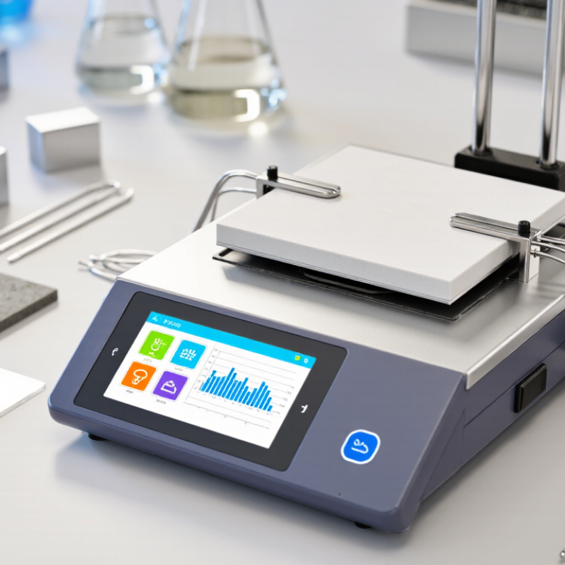
A thermal conductivity meter measures how easily heat moves through a material. Its purpose is simple: to quantify thermal conductivity, usually reported in watts per metre-kelvin (W/m·K). Lower values generally indicate better insulation. The measurement supports decisions about building envelopes, refrigeration panels, batteries, ceramics, and other engineered products.
The instrument creates a controlled temperature difference across a test specimen. Sensors record heat flow and temperature on both sides. Software then calculates conductivity using the specimen’s thickness, area, and temperature gradient. Some meters use a guarded heat-flow method, while others use transient heating. The correct method depends on the material and test standard.
This matters beyond the laboratory. UNEP’s 2023 Global Status Report for Buildings and Construction estimated that buildings consumed about 32% of global energy and produced roughly 34% of global carbon dioxide emissions in 2022. Better insulation can reduce heat loss, but only when its measured performance reflects real conditions. Moisture, surface contact, density, and sample direction can change the result. Small errors matter.
A clean reading is not always a reliable reading.
In practical testing, operators should condition samples, verify calibration, and record ambient temperature. Standards such as ASTM C518 and ISO 8301 help improve comparability between laboratories. Still, a meter does not explain every material behavior. Imperfect contact or uneven samples can distort results, so experienced technicians review the setup instead of trusting one number blindly.
What Is a Thermal Conductivity Meter and How Does It Work?
Core Principles Behind Thermal Conductivity Measurement
A thermal conductivity meter measures how easily heat travels through a material. Its core task is comparing heat flow with the temperature difference across a test sample. In simple terms, one side receives controlled heat, while the other side remains cooler. The setup matters. Sensors record temperatures at both surfaces and monitor the supplied heat. When conditions stabilize, the instrument estimates the material’s thermal conductivity.
Many meters use Fourier’s law to describe this process. Thermal conductivity is calculated from heat flow, sample thickness, and temperature gradient. A larger heat flow usually indicates better thermal conduction, assuming other conditions remain constant. Transient methods measure temperature changes over time instead of waiting for full stability. The sample must be uniform, clean, and correctly sized. Small gaps mislead. Contact resistance between the sensor and sample can reduce apparent conductivity.
Reliable measurement begins with careful preparation. I check surface flatness, clamping pressure, and sensor contact before each test. Calibration should use traceable reference materials with known properties. Room drafts, vibration, and unstable temperatures may affect results. Moisture changes can also alter porous materials. Results can drift. A careful operator records sample density, direction, temperature, and conditioning time. Still, no reading is perfectly independent of the test method. That uncertainty deserves attention when comparing materials or designing insulation systems.
What Is a Thermal Conductivity Meter and How Does It Work?
A thermal conductivity meter measures how quickly heat travels through a material. Its main components include a controlled heat source, a temperature sensor, measurement electronics, and a display or data system. The heat source creates a small temperature difference. Sensors then track the temperature change across the sample. Software converts this response into a thermal conductivity value, usually expressed in W/(m·K).
Sensor design strongly affects measurement quality. A transient hot-wire sensor uses a thin heated wire to measure temperature changes over time. It works well with liquids and powders when the sample surrounds the wire evenly. A guarded hot-plate design suits solid insulation because it directs heat through a defined path. Heat-flow sensors are useful for flat specimens, but surface contact must remain consistent. Uneven pressure, air gaps, moisture, or material direction can distort results. A meter may appear precise while measuring a poorly prepared sample.
Tips: Calibrate the instrument before important tests. Keep sample temperature stable. Remove visible air gaps around the sensor. For layered or fibrous materials, record the measurement direction. Repeat each test when possible. If readings vary widely, inspect contact pressure and moisture first. No design is perfect. Even a reliable sensor needs thoughtful handling and honest review of unusual results.
A thermal conductivity meter measures how efficiently a material transfers heat. The instrument typically includes a heat source, temperature sensors, a controlled test area, signal conditioning electronics, and software that calculates thermal conductivity from the measured temperature response.
Representative thermal conductivity at approximately 25°C: Metals generally conduct heat far more effectively than liquids, glass, or gases. Sensor selection depends on the sample: guarded hot plates are commonly used for insulation, transient hot-wire sensors suit liquids and gases, and transient plane-source sensors can test many solid materials.
What Is a Thermal Conductivity Meter and How Does It Work?
A thermal conductivity meter measures how quickly heat moves through a material. Its sensor creates a controlled temperature difference, then tracks the resulting heat flow. The instrument converts this response into a conductivity value, often reported in W/m·K. Test design matters. Solid samples may use a surface probe, while liquids often require an immersed sensor. Different methods suit different materials.
Step-by-Step Operation of a Thermal Conductivity Meter
Inspect the sample and remove dust, moisture, or visible air gaps. Check the sensor for residue or damage. Calibrate the meter with a suitable reference material before testing. This step is easy to underestimate. Place the sensor firmly against the sample, or immerse it fully in the liquid. Avoid movement during measurement. Start the test and wait until the temperature signal stabilizes. Record the conductivity value, sample temperature, test method, and room conditions. Run several measurements and compare the results. If readings vary widely, check contact pressure, sample uniformity, and calibration. I once found that a small surface gap caused a surprisingly high result.
Tips: Keep the sample and sensor near thermal equilibrium before testing. Use consistent contact pressure for every trial. For liquids, remove trapped bubbles around the sensor. Do not touch the sensing area during measurement. Clean it carefully after use. A stable laboratory temperature improves repeatability, but real materials can still behave unevenly. When results seem unusual, repeat the test instead of forcing an expected value.
| Step | Operating Stage | Key Parameter or Data | What the Meter Does | Expected Data or Quality Check |
|---|---|---|---|---|
| 1 | Select the Measurement Method | Material type and approximate thermal conductivity | The operator selects a suitable technique. Steady-state methods are commonly used for solid samples, while transient hot-wire or transient plane-source methods are often used for liquids, powders, and some solids. | The selected method must match the sample geometry, density, moisture level, temperature range, and expected conductivity. |
| 2 | Prepare the Test Specimen | Sample dimensions, surface condition, density, and moisture content | The sample is cut or formed to fit the sensor or test cell. Contact surfaces are cleaned, flat, and free from visible gaps, dust, and loose particles. | A consistent contact area and uniform sample thickness reduce contact resistance and improve repeatability. The specimen temperature should be close to the intended test temperature. |
| 3 | Stabilize the Temperature | Test temperature and temperature stability | The meter, sensor, and sample are allowed to reach thermal equilibrium before measurement. A controlled chamber or temperature stage may be used when testing at a specified temperature. | The temperature reading should remain stable during the defined observation period. Large temperature drift can cause the calculated conductivity to change even when the sample is unchanged. |
| 4 | Calibrate or Verify the Instrument | Reference material, calibration constant, and sensor condition | The meter is checked with a reference material or an internal verification routine. The measured value is compared with the certified or expected value for that reference. | The verification result should fall within the instrument’s stated accuracy or the laboratory’s acceptance limit. Calibration should be repeated after sensor replacement, damage, or a major temperature change. |
| 5 | Place the Sensor or Sample | Sensor contact, applied pressure, and sample position | The probe, hot wire, heated plate, or test cell is positioned according to the method. For contact measurements, consistent pressure is applied without deforming the sample. | The sensor should be fully covered by the specimen or have the required immersion depth. Air gaps, uneven pressure, or sample movement can create significant measurement error. |
| 6 | Apply a Controlled Heat Input | Heat input, electrical power, and heating time | The instrument supplies a known heat flow or a controlled electrical heating pulse. Temperature sensors record the temperature response at one or more locations. | The heat input should be low enough to prevent convection, moisture migration, phase change, or thermal damage, while still producing a measurable temperature response. |
| 7 | Measure the Temperature Response | Temperature difference, elapsed time, and sensor resistance or voltage | The meter measures how quickly and how far the sample temperature changes. In a steady-state system, it monitors the temperature difference across a known thickness. | A stable temperature gradient indicates that a steady-state calculation may be valid. A smooth transient temperature curve is required for transient methods. |
| 8 | Calculate Thermal Conductivity | Thermal conductivity, heat flow, thickness, area, and temperature difference | The instrument converts the measured heat and temperature data into thermal conductivity using the selected model. Steady-state relation: k = QL / (AΔT) k = thermal conductivity; Q = heat-transfer rate; L = sample thickness; A = heat-transfer area; ΔT = temperature difference | The reported unit is normally watt per metre-kelvin, written as W/(m·K). A higher value indicates that heat travels more readily through the material. |
| 9 | Check Measurement Quality | Repeatability, standard deviation, temperature drift, and test validity | The operator reviews the temperature curve, sensor contact, test duration, and any instrument warnings. The measurement is repeated when the result is unstable or outside the expected material range. | Repeated readings should agree within the laboratory’s predefined tolerance. A large spread may indicate poor contact, non-uniform material, convection, moisture movement, or an unsuitable method. |
| 10 | Record and Report the Result | Conductivity, test temperature, method, specimen condition, and uncertainty | The final record includes the measured conductivity, temperature, sample identification, dimensions, density or moisture condition when relevant, calibration status, and number of repetitions. | A complete report allows the result to be compared with other measurements. The test temperature and measurement method must always be stated because conductivity depends on both. |
What Is a Thermal Conductivity Meter and How Does It Work?
A thermal conductivity meter measures how quickly heat moves through a material. It usually creates a controlled temperature difference, then records the resulting heat flow. Steady-state systems suit insulation, ceramics, and building materials. Transient systems help test liquids, powders, and small samples faster. The application matters. The International Energy Agency reported that buildings consumed about 30% of global final energy in 2022, making insulation testing commercially important (IEA, Global Status Report for Buildings and Construction, 2023).
Accuracy depends on more than the sensor. Sample thickness, surface flatness, moisture, density, and grain direction can change the reading. A wet mineral sample may conduct heat differently from the same sample after drying. Contact resistance is another hidden problem. Even a thin air gap can distort results. ASTM C518 and ISO 22007-2 emphasize calibration, stable temperatures, and controlled test conditions. In practice, operators should record specimen conditioning and repeat measurements. A clean number can still be wrong.
Instrument limitations deserve attention. Some meters assume uniform, isotropic materials, but wood and layered composites rarely behave that way. Very low-conductivity samples may require long stabilization periods. Small samples can also suffer from edge heat loss. Published uncertainty may increase when measurements move beyond the instrument’s calibrated range. NIST guidance on thermal measurements stresses traceable calibration and uncertainty evaluation. The difficult part is not pressing the button. It is deciding whether the result represents the real material.