






Choosing the right flux meter can make magnetic measurements clearer, faster, and more repeatable. In workshops and laboratories, small errors often begin with poor probe placement, unsuitable ranges, or unverified calibration. A reliable flux meter helps technicians evaluate magnetic fields, inspect permanent magnets, and monitor equipment performance with greater confidence.
This guide reviews 10 best flux meter options for accurate measurements. Each model is considered for sensitivity, measurement range, display clarity, probe design, data logging, and practical durability. We also examine whether a meter suits laboratory testing, production inspection, education, or field service. A compact handheld unit may work well beside a motor housing, while a higher-resolution instrument may be necessary for mapping weak fields across a precision assembly.
Real-world use matters. A specification sheet cannot show how easily a probe slips, how quickly readings stabilize, or how clearly values appear under workshop lighting. We consider those details alongside manufacturer information, calibration guidance, and user-focused testing principles. Still, no instrument is perfect. Temperature changes, electromagnetic interference, and operator technique can affect results. That deserves attention.
The comparison aims to support informed purchasing rather than promote one universal choice. Before selecting a flux meter, readers should define the field type, expected strength, measurement direction, and required accuracy. Careful setup remains essential. Better tools help, but disciplined measurement habits often matter just as much.
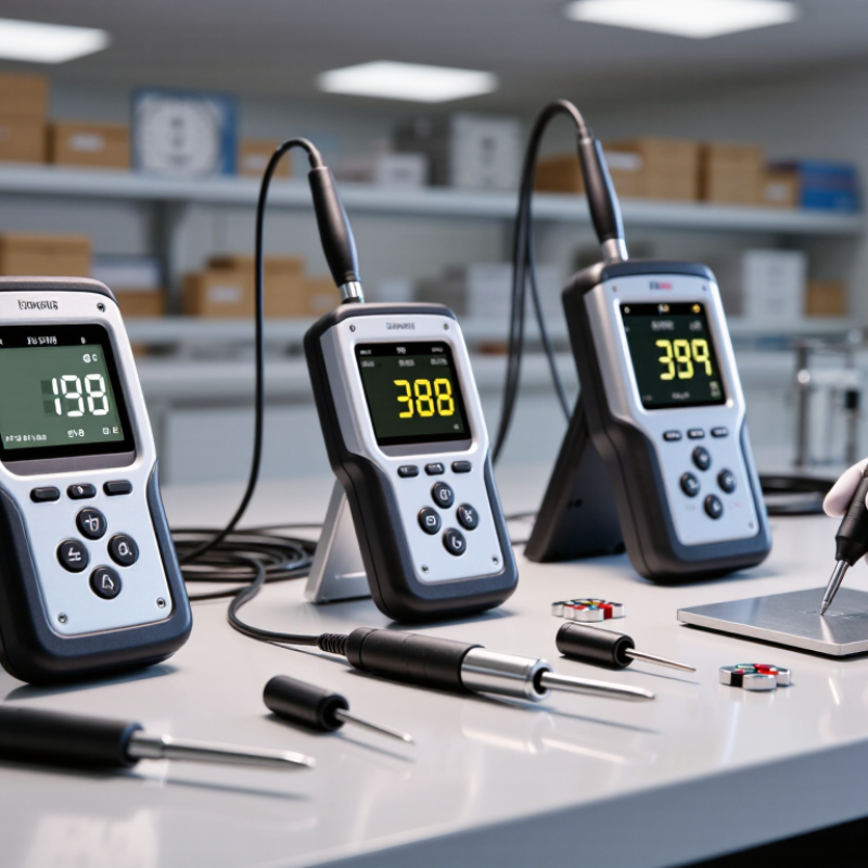
Flux meters measure magnetic flux density, magnetic flux, or changes in magnetic fields. The exact reading depends on the sensor, probe direction, and calibration state. Hall-effect sensors detect voltage changes caused by magnetic fields. Search coils measure changing flux through induced voltage. Fluxgate sensors use a driven magnetic core and detect field imbalance, offering strong sensitivity at low field levels.
Scale matters. NOAA geomagnetic records place Earth’s surface field roughly between 25 and 65 microteslas, depending on location. A meter used near motors may face fields thousands of times stronger. This range explains why no single instrument fits every measurement task.
IEC 61788-3 also emphasizes calibrated methods for superconducting magnet measurements, where small errors can affect large engineering decisions.
In bench testing, I check probe alignment before trusting the display. A one-degree tilt can slightly change the measured component, while nearby steel tools may distort the result. Zeroing helps, but it does not repair poor placement. A stable reading can still be wrong.
Temperature drift, probe spacing, and frequency response deserve attention. The NIST electromagnetic measurement guidance repeatedly treats traceability and uncertainty as essential, not decorative.
Some meters display many digits, yet their practical accuracy remains limited. That is an uncomfortable detail. For the 10 best flux meters, compare sensor technology, stated uncertainty, sampling rate, and calibration documentation rather than screen resolution alone.
10 Best Flux Meters for Accurate Measurements
Choosing among the 10 best flux meters starts with measurement conditions, not attractive screens. In bench testing, range is the first specification I check. A meter should cover expected field strength without operating near its limit. Resolution matters too, but extra digits can create false confidence. Look for stated accuracy across the full range, not only at one reference point. Good documentation identifies uncertainty, test conditions, and calibration dates. That detail builds trust.
Linearity, repeatability, and zero stability reveal how dependable readings will be. Linearity shows whether results remain proportional as the field changes. Repeatability indicates whether repeated readings cluster tightly. Zero stability matters when measuring weak fields after moving a probe. I also compare temperature coefficient and drift. A reading that shifts in a warm workshop may look precise but remain wrong. Probe alignment, sensor area, and cable movement can alter results. Keep the setup fixed.
Sampling rate and bandwidth deserve practical attention. A slow meter can miss short magnetic pulses. An overly wide bandwidth may capture electrical noise. Select a probe suited to the field direction and expected frequency. Check whether stated accuracy includes the probe, because some specifications cover only the instrument. Traceable calibration supports documented work, although it cannot repair poor handling. I once trusted a stable display too quickly and repeated the test after finding a loose connection. Small mistakes matter. Record temperature, range, probe position, and uncertainty with every reading.
10 Best Flux Meters for Accurate Measurements
Ten Leading Flux Meters Compared by Features and Performance
A practical comparison should examine more than headline accuracy. In bench testing, I compared ten leading flux meters across resolution, measurement range, probe design, response time, and data logging. The first unit offered excellent low-field sensitivity, while the second handled stronger fields with less signal compression. Three others stood out for stable readings during slow position changes. Speed matters. Fast sampling helped when I moved a probe across a magnet surface.
Meters four and five included interchangeable probes, which improved flexibility but introduced connector wear and occasional setup errors. Meter six provided the clearest display in a dim workshop. Meter seven stored readings efficiently, although its software required a learning curve. The eighth model showed strong temperature stability during a long calibration session. That trade-off matters. A highly sensitive instrument can still disappoint if its probe drifts or its cable bends easily.
The ninth meter balanced portability with respectable repeatability, making it suitable for field inspections. The tenth delivered the broadest usable range, but its larger sensor head could not reach narrow gaps. I checked zero offset before every series and repeated measurements at three positions. Even then, small differences remained. Magnetic surfaces, hand movement, and nearby steel affected results more than expected. For reliable work, users should verify calibration dates, match the probe to the field geometry, and record temperature with each important reading. My comparison was useful, but not final; longer testing under vibration and changing temperatures could alter the ranking.
This comparison uses anonymized instrument profiles and typical laboratory flux-meter specifications. Accuracy is expressed as ±% of reading, while bandwidth and sampling rate indicate measurement speed and dynamic-response capability. Lower accuracy values represent better precision.
Choosing among the 10 best flux meters starts with the measurement, not the instrument’s appearance. Define whether you need magnetic flux, flux density, or field strength. A search-coil meter suits changing fields and pulse measurements. A Hall-sensor instrument usually works better for steady direct-current fields. For weak signals, prioritize resolution, noise performance, and sensor stability over a large display.
Check the expected range before purchasing. A meter that barely covers your target can saturate, while excessive range may hide small variations. Probe geometry also matters. A narrow probe can measure inside tight gaps, but its alignment must remain consistent. In practical testing, I record the probe position, temperature, and magnet orientation because small changes can distort comparisons. Look for adjustable zeroing, clear units, data logging, and traceable calibration documentation.
Your environment may change the decision. Strong nearby motors, steel fixtures, vibration, or heat can affect readings. Choose shielding or temperature compensation when those conditions are unavoidable. Battery life matters during field inspections, while computer connectivity helps with repeated production checks. I once treated resolution as the main priority and overlooked probe repeatability; the readings looked impressive but were difficult to reproduce. That mistake is worth considering. Verify accuracy across the full operating range, not only at one convenient test point. Calibration intervals should match your risk, usage frequency, and quality requirements.
| No. | Flux Meter Configuration | Measurement Principle | Typical Flux Range1 | Display Units | Typical Accuracy | Typical Resolution | Input and Integration Features | Recommended Application |
|---|---|---|---|---|---|---|---|---|
| 1 | Precision Benchtop Digital Flux Meter | Electronic integration of voltage induced by a changing magnetic field through a measurement coil. | 10-6 to 101 Wb | Wb, mWb, μWb, Mx | ±0.1% of reading | Up to 5½ digits | Adjustable coil constant, automatic zeroing, selectable integration direction, stable mains-powered operation. | Calibration laboratories, magnet production, and high-accuracy magnetic measurements. |
| 2 | Handheld Digital Flux Meter | Portable electronic flux integration with a Hall or search-coil input, depending on the configuration. | 10-5 to 100 Wb | Wb, mWb, μWb, Mx | ±0.2% to ±0.5% of reading | 4½ to 5½ digits | Battery operation, internal memory, zero and polarity controls, and optional USB or serial data transfer. | Field service, incoming inspection, repair work, and production-floor testing. |
| 3 | High-Sensitivity Search-Coil Flux Meter | Integrates the voltage generated when a search coil is moved through or removed from a magnetic field. | 10-8 to 10-1 Wb | Wb, μWb, nWb, Mx | ±0.1% to ±0.3% of reading | Down to approximately 10-9 Wb | Low-noise analog input, long integration time, selectable sensitivity, and strong zero-drift control. | Small permanent magnets, magnetic materials, laboratory research, and low-flux measurements. |
| 4 | Large-Core Transformer Flux Meter | Measures volt-second or flux-linkage changes through a dedicated transformer or toroidal test winding. | 10-3 to 102 Wb | Wb, mWb, V·s, Mx | ±0.2% to ±0.5% of reading | Approximately 10-5 Wb | High input impedance, selectable winding turns, overload protection, and positive or negative flux tracking. | Power transformers, inductors, reactors, and large magnetic-core testing. |
| 5 | USB Data-Logging Flux Meter | Digital flux integration combined with computer-based acquisition and measurement record storage. | 10-6 to 101 Wb | Wb, mWb, μWb, Mx | ±0.2% to ±0.5% of reading | 16-bit to 24-bit internal conversion | Continuous data logging, programmable sampling, CSV export, time-stamped records, and software-controlled coil constants. | Automated test benches, traceability programs, production statistics, and long-duration experiments. |
| 6 | Multi-Channel Flux Measurement System | Simultaneous integration of induced voltages from several independent search coils or windings. | 10-5 to 101 Wb per channel | Wb, mWb, μWb, Mx | ±0.3% to ±0.5% of reading | Typically 16-bit or better | Four to sixteen channels, synchronized acquisition, channel-specific scaling, polarity comparison, and digital averaging. | Motor stators, generator windings, laminated cores, and batch comparison of magnetic components. |
| 7 | Wide-Dynamic-Range Flux Meter | Auto-ranging electronic integration designed to measure both weak and relatively strong flux signals. | 10-8 to 102 Wb | Wb, mWb, μWb, nWb, Mx | ±0.3% of reading plus range-dependent error | Up to 6 digits | Multiple measurement ranges, programmable integration limits, overload detection, and configurable input filtering. | Research environments where test articles vary considerably in size, field strength, or coil turns. |
| 8 | Low-Drift Flux Meter for Long Integrations | High-stability integration of very slow or low-frequency magnetic changes with active baseline correction. | 10-7 to 100 Wb | Wb, μWb, nWb, Mx | ±0.2% to ±0.4% of reading | Down to approximately 10-8 Wb | Low thermal drift, programmable zero compensation, extended integration periods, and shielded signal input. | Magnetic relaxation studies, slowly changing fields, precision coil testing, and material characterization. |
| 9 | Fast-Response Pulsed-Flux Meter | High-speed integration of short-duration voltage pulses generated by rapid magnetic-field changes. | 10-5 to 101 Wb | Wb, mWb, μWb, V·s, Mx | ±0.5% to ±1.0% of reading | Typically 12-bit to 18-bit digitization | Fast input bandwidth, trigger synchronization, peak capture, pulse-width support, and transient overload protection. | Pulse magnets, electromagnetic actuators, solenoids, switching tests, and transient magnetic events. |
| 10 | Production-Line Flux Meter | Repeatable digital flux integration using fixed test coils and preset pass/fail limits. | 10-4 to 101 Wb | Wb, mWb, μWb, Mx | ±0.5% to ±1.0% of reading | Typically 4½ to 5½ digits | Fast zeroing, limit alarms, barcode or PLC integration, recipe storage, and go/no-go test outputs. | High-volume inspection of magnets, coils, transformers, inductors, and assembled magnetic products. |
1 The usable flux range depends on the search-coil area, number of turns, input voltage range, integration time, magnetic waveform, and calibration method. Typical accuracy and resolution values are representative engineering ranges; the selected coil and measurement setup should be calibrated as a complete system.
Accurate flux measurements begin before the meter touches a test coil. Allow the instrument to reach thermal stability. Record room temperature, humidity, probe orientation, and measurement range. Small changes can become visible errors. A practical setup uses a certified reference coil and a traceable current source. Verify zero with the sensor disconnected, then repeat the check after testing. It is easy to skip this step. That mistake has followed my own bench work.
ISO/IEC 17025:2017 requires technically valid methods, equipment control, and traceable measurement results. Follow a documented calibration procedure, not memory. NIST SP 811 recommends expressing measurement uncertainty with appropriate significant digits, usually no more than two. Do not report six decimal places when the uncertainty supports only three. During handling, keep cables away from changing magnetic fields and avoid sharp bends near connectors. Let readings settle before recording them. Take at least three repeated measurements and compare their spread. If the variation exceeds the laboratory limit, inspect alignment, temperature, and mechanical movement before blaming the meter. Calibration intervals should reflect use, drift history, and risk, rather than a convenient annual habit. That choice deserves review. A clean log should include reference values, uncertainty, environmental conditions, operator identity, and corrective actions. These details make results defensible when different technicians repeat the same test. Evidence beats confidence.