






7 Best Contact Temperature Sensors for Accurate Readings?

Choosing a contact temperature sensor is not as simple as picking the most accurate number on a product page. The right choice depends on what you are measuring, how quickly temperatures change, and how the probe touches the surface or material. A sensor used in a laboratory may not suit a hot pipe, food process, or moving machine part. Small details matter.

This guide compares seven contact temperature sensors, including common thermocouple, RTD, and thermistor options. It looks at useful factors such as measurement range, response time, accuracy, probe design, durability, and compatibility with readout equipment. A fast probe can be convenient, but it may sacrifice stability. A highly accurate sensor can also give poor results if it is installed badly or used outside its rated conditions. That part is easy to overlook.

The goal is to help you match sensor characteristics to real measurement needs, rather than treat a single specification as proof of quality. Check manufacturer documentation, calibration information, and operating limits before buying or relying on readings. No comparison can account for every installation, and the “best” choice may change with the surface, mounting method, and surrounding conditions. Even a careful selection deserves a practical test.
7 Best Contact Temperature Sensors for Accurate Readings?

How Contact Sensors Measure Heat: Conduction, Thermal Lag, and Surface Error

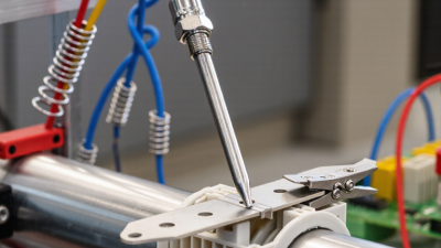
A contact temperature sensor does not read a surface instantly; heat must travel into its sensing element. With a thermocouple or resistance sensor, that transfer happens through the probe tip by conduction. Firm, stable contact matters. Small air gaps matter. Even a polished metal plate can give a misleading result if the probe rocks or touches only an edge.

Thermal lag is the delay before a sensor approaches the surface temperature. A thick probe, large sensing bead, or heavy clamp stores more heat and usually responds more slowly than a fine, lightly mounted tip. The reading may drift after placement, so watch for a stable trend instead of trusting the first number. Still, stable does not always mean correct. The probe stem can carry heat toward cooler air or a warmer hand, shifting the measurement.

Surface error adds another complication. Oxide, paint, curvature, roughness, and uneven pressure all affect the contact path. On a small pipe, a spring clamp and thin interface layer may improve repeatability, but excess paste can spread heat or conceal poor placement. Check the sensor against a trusted reference, keep mounting pressure consistent, and note where the tip sits. I’d still question a single neat reading. Repeating the measurement nearby can reveal temperature gradients the display cannot explain.

7 Contact Temperature Sensor Designs: Response Time and Surface Accuracy

Representative time-to-90%-of-final-reading (t90) ranges. Shorter response times generally indicate less thermal lag.

Sensor response depends on construction, contact pressure, mounting, and the measured material. Surface readings can also differ from the true surface temperature when heat conducts into the probe or contact is imperfect. These ranges are illustrative, not a standardized ranking; check the sensor’s specifications and test it in its intended setup.

Seven Sensor Options: Thermocouple, Pt100, NTC, IC, Bimetal, Fiber, and Probe

Thermocouples suit wide temperature ranges and respond quickly, but their output needs careful calibration. Pt100 sensors offer stable, repeatable readings, making them useful when small changes matter. Their wiring and measurement circuit can add complexity. NTC thermistors are highly sensitive over a narrower range, though their response is nonlinear. That matters. A lookup table or suitable circuit helps translate resistance into temperature.

Integrated-circuit sensors simplify electronic designs, but many have limited operating ranges and need close contact with the measured surface. Bimetal sensors are rugged and need no powered readout, yet they usually provide less precise measurements. Fiber-optic sensors resist electromagnetic interference and can work in electrically noisy settings, though installation and readout equipment may be specialized. Probe sensors are a practical format for liquids, pipes, or inserted measurements; they are not a sensing technology by themselves. A probe may contain a thermocouple, Pt100, or another element. Not always obvious. In real use, mounting pressure, surface cleanliness, and thermal paste can shift readings. I would check those details before blaming the sensor.

7 Best Contact Temperature Sensors for Accurate Readings? — Seven Sensor Options: Thermocouple, Pt100, NTC, IC, Bimetal, Fiber, and Probe
Sensor option How it measures temperature Typical operating range Typical accuracy Key strengths Limitations and suitable uses
Thermocouple Two dissimilar metal wires generate a small voltage related to the temperature difference between the measuring and reference junctions. About −200°C to 1,250°C for common types and assemblies; the usable range depends on thermocouple type, sheath, and environment. Often around ±1.5–2.5°C or ±0.4–1% of reading, depending on type and tolerance class. Wide temperature coverage, rugged construction, and fast response with a small exposed junction. Requires reference-junction compensation; accuracy and stability can be lower than a precision RTD. Common in ovens, engines, and industrial equipment.
Pt100 RTD A platinum element changes electrical resistance in a predictable way; a Pt100 has a nominal resistance of 100 Ω at 0°C. Typically about −200°C to 600°C, depending on the probe design and insulation. IEC 60751 Class A tolerance is ±(0.15 + 0.002 × |t|)°C from −30°C to 300°C; other classes are available. Good repeatability, stability, and accuracy over a broad range; well suited to process measurement. Usually costs more and may respond more slowly than a fine-wire thermocouple. Lead-wire resistance and measurement current require attention.
NTC thermistor A semiconductor’s resistance decreases as its temperature increases. Commonly about −50°C to 150°C; limits depend on the thermistor and its packaging. Approximately ±0.1–1°C is achievable with a selected or calibrated sensor over a specified range; uncalibrated accuracy varies. High sensitivity, compact size, and low cost; useful for detecting small changes over a limited temperature range. Nonlinear response and a narrower operating range than many RTDs or thermocouples. Common in appliances, batteries, and electronics.
Integrated-circuit (IC) sensor Electronic circuitry on a semiconductor chip measures temperature and provides an analog or digital output. Many common devices operate over approximately −55°C to 150°C; the exact limits are device-specific. Often about ±0.5–2°C over a specified range, depending on the device and operating conditions. Simple electrical interface, compact size, and convenient digital outputs on many models. Operating range and heat exposure are limited compared with industrial probes. Best for circuit boards, electronics, and nearby surfaces.
Bimetal thermometer Two bonded metals expand at different rates, bending a strip or coil that moves a pointer or operates a switch. Common dial instruments cover ranges such as −50°C to 500°C; the available range depends on the instrument. Often around ±1–2% of full scale, but specifications vary by instrument and range. Needs no electrical power, is simple to read, and can be mechanically robust. Generally slower and less precise than calibrated electronic sensors. Useful for local indication in tanks, pipes, and HVAC equipment.
Fiber-optic temperature sensor Temperature is inferred from changes in an optical signal, such as fluorescence decay or wavelength shift, at the sensing tip. System-dependent; many contact systems cover roughly −200°C to 300°C, while specialized designs can extend beyond this. Often about ±0.1–1°C for suitable systems under specified conditions; performance depends on the sensing method and calibration. Immune to electromagnetic interference and electrically nonconductive at the sensing point. Requires an optical interrogator and can be more costly than conventional sensors. Useful near strong electromagnetic fields or high voltage.
Contact probe assembly A metal probe transfers heat from the measured object to an internal element, commonly a thermocouple, RTD, or thermistor. Element- and construction-dependent; many general-purpose probes operate from about −50°C to 250°C. Determined mainly by the sensing element, calibration, probe construction, and contact conditions. Provides a practical, protected contact tip for surface, liquid, or penetration measurements; available in many shapes. “Probe” describes the assembly, not a sensing principle. Contact pressure, placement, and thermal lag affect readings; choose the embedded element for the required range and accuracy.

RTD Accuracy: IEC 60751 Class A Pt100, ±(0.15 + 0.002|t|)°C

An IEC 60751 Class A Pt100 suits processes needing repeatable contact readings, not merely a plausible display. The standard sets tolerance at ±(0.15 + 0.002|t|) °C, with t measured in degrees Celsius. At 0 °C, that is ±0.15 °C; at 100 °C, it becomes ±0.35 °C. These figures come from IEC 60751:2022 and describe sensor tolerance under specified conditions. Not total system accuracy. That distinction matters beside a hot pipe, where a loose clamp or shallow insertion can skew readings.

A Pt100 has a nominal resistance of 100 Ω at 0 °C; near that point, resistance changes by about 0.385 Ω per °C. Long two-wire leads add resistance, so four-wire connections can reduce lead-related measurement error. NIST Special Publication 250-91, on resistance-thermometer calibration, describes comparison against reference standards as part of traceable calibration. Yet wiring and installation still matter. On paper, the tolerance looks crisp. In practice, I would record insertion depth, wiring, and calibration date beside each reading. I might still miss a temperature gradient.

Thermocouple Accuracy: IEC 60584 Type K Class 1, ±1.5°C or 0.004|t|

For a Type K thermocouple, IEC 60584 Class 1 specifies a tolerance of ±1.5°C or ±0.004 × |t|, whichever is greater. Here, t is the measured temperature in degrees Celsius. At 200°C, the limit is ±1.5°C; at 500°C, it is ±2°C. That distinction matters. The tolerance describes the sensor’s permitted deviation under specified conditions, not a guarantee that every installed measurement will be equally accurate.

In practical use, the displayed reading also depends on the measuring instrument, reference-junction compensation, wiring, and installation. A probe pressed against a metal pipe may respond differently from one immersed in a moving liquid. Surface contact, airflow, and response time can all shift a reading. Not the whole story. When checking a sensor, compare it with a suitable reference at the temperatures it will actually encounter, and inspect the contact point and connections. I have seen a neat-looking reading inspire too much confidence; repeat measurements can still vary. Class 1 is a useful specification, but careful setup and verification make it meaningful.

How to Choose: Temperature Range, Accuracy, Response Time, and Mounting

Choose a contact temperature sensor by matching its range to the real operating conditions. Check the specified limits, including brief heat spikes, cold starts, and cleaning cycles. A probe used on a warm pipe may not suit a hot oven wall. Leave a safety margin. Also check accuracy at the temperatures you will actually measure; a specification near room temperature may not apply across the full range.

Response time depends on the sensor’s size, construction, and contact with the surface. A small, firmly attached probe usually reacts faster than a heavy one, but fast readings are not always more useful. If the temperature changes slowly, stability may matter more. Look for the stated response time and the test conditions behind it. Those details are easy to overlook.

Mounting can make or break the reading. Clean the contact spot, secure the sensor evenly, and keep it away from drafts or nearby heat sources. For a curved pipe, use a mount that holds the sensing tip flush against the metal; a loose edge can measure the air gap instead. Insulation over the sensor may reduce ambient influence, though it can also slow response. A tidy installation can still be wrong, so compare readings with a trusted reference under normal working conditions.